Back to the homepage | |||||
Bi-Axial-Sun-Tracking-System
|
|||||
CONTENT: versions | extensions/options | system description | specifications | price list |
IMAGES: gear parts and options || MORE IMAGES AND INFO |
|
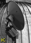
A system approved since more than a decade in heavy duty (image J & image K) consisting out of an outdoor and an indoor unit:
The usage of the positioning system could be divided into two function areas:
Important information: The accuracy of the system is so high that under favourable conditions distances of up to 200 m between mirror and goalpoint are achievable! Complete, ready Heliostat systems you can find at Heliostat (www.egis.eu/Helio_us.html). |
VERSIONS | back to the beginning | |
DISPLAY-READOUT | ||||||||||||||
operation status | mode | time | activity | day cycle | azimuth angle | elevation angle | ||||||||
RUN | M | 15:34:48 | Go | S | AZ123.5 | EL015.2 | ||||||||
CAUTION: Not all function are available on all versions and for each operating mode. |
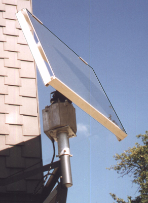
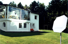
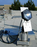
At the 'University of California' in Merced/USA the EGIS SolarTracker is used for concentrating daylight onto commercial buildings. |
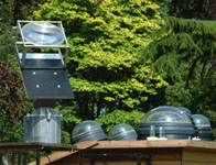
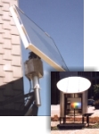
The Institution for thermodynamics and heat technology at the university of Stuttgart/Germany is calibrating 'pyranometer' with this installation. You can see the EGIS light direction finding tube in operation at the left margin of the mounting surface. |
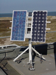
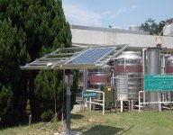
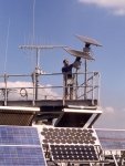
EGIS on Taiwan (China) at 'ITRI' (Industrial Technology Research Institute in Hsinchu) a testing station for PV modules and solar collectors |
EXTENSIONS & OPTIONS | back to the beginning | |
|
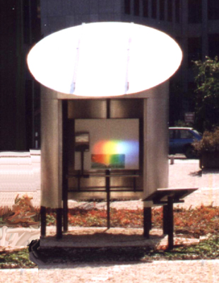
As shown here, the heliostat targets an optical prism to divide the spectrum of light as a light fraction demons- tration (Energiegarten Siegen/ Westf./Germany). | two SolarTracker in duty at "College for Technics & Business" in Flensburg/Germany |
the EGIS- Heliostat in duty research property |
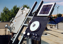
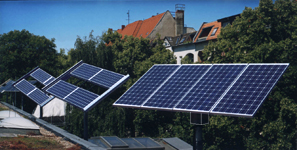
Six EGIS rotors in duty at University Dortmund/Germany (Dep. energy research). All of them are carrying approx. 6 m2 different brands and sorts of PV modules. More details about this installation |
SYSTEM DESCRIPTION | back to the beginning | |
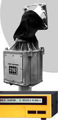
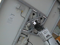
The azimuth-elevation turning system consists out of the rotor outdoor unit EPR203X as well as out of the indoor unit EPS103X. There are no additional parts necessary between "mast-holders" and "panel/reflector".
The rotor outdoor unit moves the object to be positioned fully automatically and microprocessor controlled on single positions or on tracks. For this in the rotor-outside-part, made out of a weatherproof aluminum pressure die cast, two separate 24 volts motors are installed.
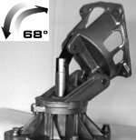
The u. m. azimuth elevation turning system moves, in standard-version, the objects in a 180° azimuth area. In elevation range the system suffers an elevation of 68°. Where exactly this lifting is used is up to the user: if elevation angle 0° until 68° or 25° until 90°. The system is doing this all very quietly and therefore, in contrast to many a wailing actuator motors, without boring the neighbors, naturally expectable at such a system.
The only adjustment during montage and installation of the rotor-outside-unit is rough northern-south-alignment of the alu die cast housing. Therefore only rough because all eventually needed corrections can be done at the indoor unit. Consequently we have arrived now the technology of the operation and control unit. This is to be understood as a switching and computing center, the heart of the plant. The heart consists out of a quick 8-bit-microcontroller and allows the technicians under the users a real eldorado of programming. Already the assembler will be informed of incorrect or missing connections. So the control box contains e.g. an electronic blocking and overload protection, run direction supervision and related clear-text-information.
This correction causes the control computer to save the data of the now exactly gotten sun position and the previously already entered data for later use. Immediately after that you may switch to "RUN" and the rotor will track in good quality.
Comfortably and simple - is installation. However how behaves the system in everyday-business? Via front keys of the control box comfortably correct east-west-deviations. Or you take full control over the whole system via the key field.
One of the most outstanding performance features of the system is its ability to cope with high wind speeds. Proved by Finite elements calculation for material and shape of the load carriing parts. You will recognize immediately the high durability and stiffness of the rotor aluminum-casing. However how does it look indoors? Here some information for the technician belonging the construction of the rotor: |
|
bearings
|
Apart of this now see here the different "nice trifles":
It gets particularly interesting with the extended versions:
|
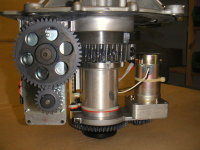
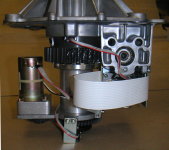
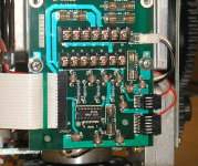
gear parts inside rotor housing | rotor terminal board |
SPECIFICATIONS | back to the beginning | |
OPERATIONAL COMPUTER: EPS-103 mod. Solar | |||||||
power supply | 223/115 Volt AC or | ||||||
24 Volt DC | |||||||
consumption | 16 VA Standby; max. 130 VA or | ||||||
7.5 VA Standby; max. 80 VA | |||||||
display and information | LCD-Diplay | ||||||
programmable memories | 64 KB RAM | ||||||
motor-supply-voltage | 24 Volt DC | ||||||
internal resolution: | azimuth | 0,0100°/pulse | |||||
elevation | 0,0025°/pulse * | ||||||
analogous signal range | 0.2 to 12 volt DC > 100 kOhm | ||||||
analogous input clock rate/resolution | about 250 Hz | ||||||
dimensions | 300 mm x 80 mm, depth of 200 mm | ||||||
weight | 4 kg | ||||||
carton-package (L x W x H) | 39 x 29 x 15 cm | ||||||
temperature limits: | operational | 5 °C to +40 °C | |||||
survive & storage | 15 °C to +60 °C | ||||||
ROTOR: EPSR-203 mod. | |||||||
special attributes | 2 separate motors for azimuth and elevation-movements | ||||||
motor voltage | 24 Volt DC | ||||||
power supply consumption | max. 20 watts | ||||||
'control device to rotor' cable | 10 x 0,6 mm2 geschirmt (telephone cable proven!) | ||||||
At version "SolarTracker Pro" these 10 wires are individually shielded. | |||||||
4 x 1,0 mm2 (for motor power supply) | |||||||
at lengths over 50 m 1.5 mm2 | |||||||
control-type | actuation spindles and teeth gears | ||||||
max. azimuth turn range | 360° * | ||||||
max. elevation range | 90° * | ||||||
return accuracy (part load): | 0,3° (version with 68° EL) | ||||||
In end positions of movement-lifting greater deviations may appear. | |||||||
tracking resolution | > 0.2° * | ||||||
speed: | azimuth | approx. 4°/sec. | |||||
elevation | 68° version: approx. 2°/sec. or 7°/sec. * | ||||||
usable payload | approx. 50 max. 85 kg * (exc. 50 kg counter balance is needed) | ||||||
casing | alu, pressure-casting, weather-constant | ||||||
dimensions: | diameter | approx. 318 mm | |||||
height | approx. 625 mm | ||||||
Click here to see a dimension sketching! | |||||||
weight | 27 33 kg * | ||||||
carton package (L x W x H) | 75 x 34 x 41 cm | ||||||
mechanical connections: | reflector | see sketching | |||||
mast | flat = approx. 240 mm Ø with 4 threads (screws delivery included) | ||||||
max. reflector size | 3 up to 6 m2 * | ||||||
max. wind speed | 62 km/h in operation, | ||||||
up to 160 km/h belonging on panel size and static load | |||||||
90° version: restriction to 50 % of reflector area and wind-/pay load! (strength proof) | |||||||
temperature limits: | operational | 20 °C to +65 °C | |||||
survive & storage | 30 °C to +65 °C | ||||||
* | = | according to version |
Some figures for 24 V stand-alone & accu operation:
|
|||
PRICE LIST | back to the beginning | |
VERSION | | (excl. VAT) EURO | |||||||||
SolarTracker | rotor incl. control box AZ 180° / EL 68° | 2 298.00 | ||||||||
version: standard/AC 230/115 V AC (effective power dissipation 13 W) | ||||||||||
or | ||||||||||
version: standard/DC 24 V | ||||||||||
SolarTracker Pro | as above, however with solid-state relais | 3 298.00 | ||||||||
OPTIONS | | (excl. VAT) EURO | |||||||||
DC 12 V | 12 V power supply for version DC 24 V | 478.35 | ||||||||
Analog-Input | analogous signal-dependent positioning load/power dependent | 748.00 | ||||||||
Data-Interface | interface (RS 232 C) | 798.00 | ||||||||
GPS-Capture | GPS-Software-Interface | 549.00 | ||||||||
is only supplied in combination with Data-Interface | ||||||||||
MotionControl | speed control and regulation for SolarTracker Pro only | 989.00 | ||||||||
GR-19 | mounting of the SolarTracker Pro control electronics in 19" casing (2 HE, incl. illum. display) (image H) | 998.00 | ||||||||
AZ360 | expansion on 360° azimuth turn-area | 798.00 | ||||||||
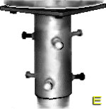
Masttop/Rotor Table |
mechanical interface between rotor and mast (max. 89 mm Ø) | 198.00 | ||||||||
Masttop/Rotor Table |
as above, however for max. 128 mm Ø mast | 298.00 | ||||||||
incl. mounting material (image E) | ||||||||||
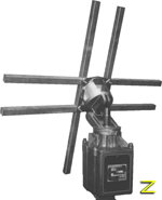
Panel holder | universal connecting adapter between panel/reflector and rotor-head | 298.00 | ||||||||
Hot-dip galvanized, steel square tube (50 x 30 x 2 mm). Length 1 m. Connection material included in delivery (example applications/image Z). | ||||||||||
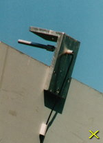
Light direction finding tube | for the easy and comfortable finding of the direction/position with the maximum of light | 378.00 | ||||||||
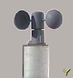
Wi-S1 | wind-speed-sensor/shell-anemometer | 317.35 | ||||||||
All customers that are interested in advanced versions we offer a special service: now order the basic version and get the expansions immediately after availability (advice to soft- and hardware expansions). By that we secure that no financial and no functional decrease occurs on later deliveries! |
Please tell us about your particular special application!
Technical improvements are subject of change! |
CONTENT: versions | extensions/options | system description | specifications | price list |
IMAGES: controls and connectors | gear parts and options || MORE IMAGES AND INFO |
EGIS Cloud |
E G I S
EQUIPMENT GESELLSCHAFT für INTERN. ELEKTRONIK SYSTEME GmbH |
Flutstraße 34 36
D63071 OFFENBACH/MAIN Tel.: 069 / 85 83 27 Fax: 069 / 85 78 63 |
|
<< Homepage | 20 minutes from Airport Frankfurt 20 minutes to Frankfurt City | E-Mail: Solar@egis.eu |