| University Budapest/Hungary: Institute for Highfrequency Technics | ||
 |
 |
|
 |
Back to the homepage | 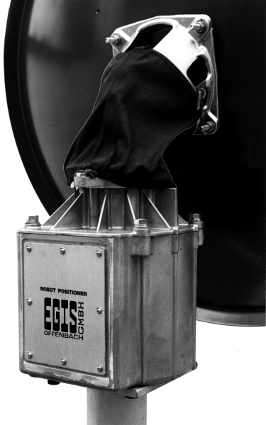 |
|||

|
|||||
|
|||||
| CONTENT: base version | extensions/options | system description | specifications | price list | news |
| IMAGES: gear parts and options || MORE IMAGES AND INFO |
|
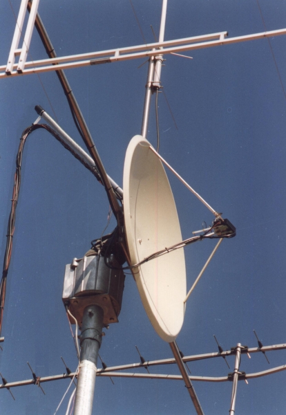 |
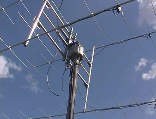
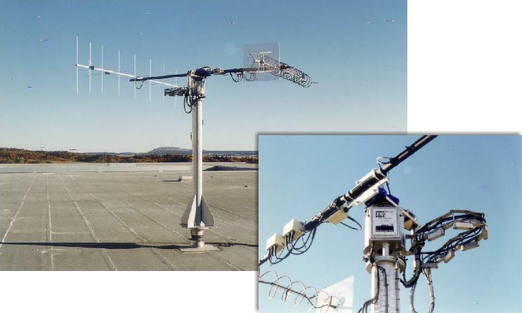
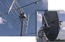
"HAM" radio application with parabolic and yagi antennas |
 |
It is the smallest indeed (shown straight right), however, a fully professional one too – the EGIS rotor in duty at "EUTELSAT" in Paris/France |
 |
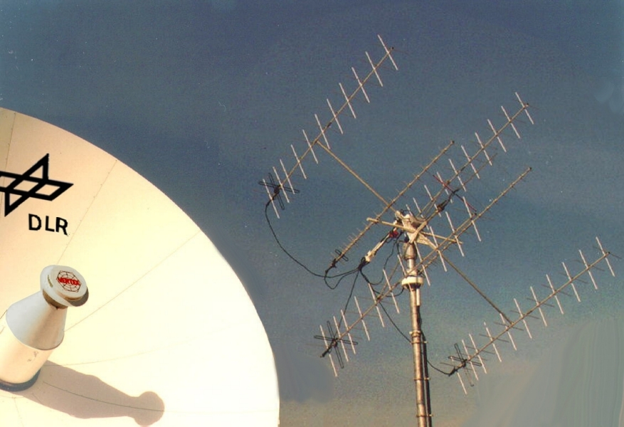
EGIS rotors at the USA-Antarctic-Program with Yagi antennas for ATS-3 satellite (also used for commmanding & telemetry VHF on GOES-3) 149 MHz & 137 MHz and LES-9 satellite 302 MHz & 249 MHz. All of the above antennas are used in support of the "United States Antarctic Program". The 'Malabar Satellite Operations Center' of the University of Miami provides communications to various research stations on the antarctic continent, including the 'Geographic South Pole station', and 'Palmer station' in the antarctic. Mostly EGIS rotors are used for antenna tracking. |
 |
The EGIS-Rotor in use by the Foreign Secretary of the German Government in Bonn |
 |
EGIS rotors in a ground station at the "U.S. Air Force Academy" in Colorado Springs, USA. Use: Mission Control. |
| a. BASE VERSION | back to the beginning | |
|
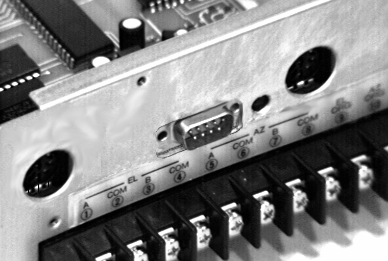
| * | = | Receiver-Interface: The 4 wires, normally routed from the satellite receiver to the linear actuator motor on the roof, are connected to the terminals on the rear panel of our control unit. Now it will be possible to select the individual satellites directly by means of the receiver's remote control in the same way as with an actuator – but more accurately and from "horizon to horizon", even at the ends of the "clark belt"! |
| ** | = | A very rigidMechanical connection between antenna and rotor is required for AUTOFOCUS operation. It must be possible to correlate signals measured by the satellite receiver accurately with a specific antenna direction (which means direction of the rotor). AGC signals shall only indicate true field strength-related changes, without time shifts, picture contents fluctuation and "spike" influences. |
| *** | = | To minimize fuel consumption older satellites are "inclined" in higher amplitudes. More than 50 % of all satellites are already in "inclination orbit". And their percentage is growing steadily! Permanent reception with greater antennas is not possible all over the time. One big advantage of this rotor system is the tracking of such satellites: even before the TV viewer will recognize any loss of picture quality, the antenna will follow the position of the satellites automatically, quickly and perfectly! |
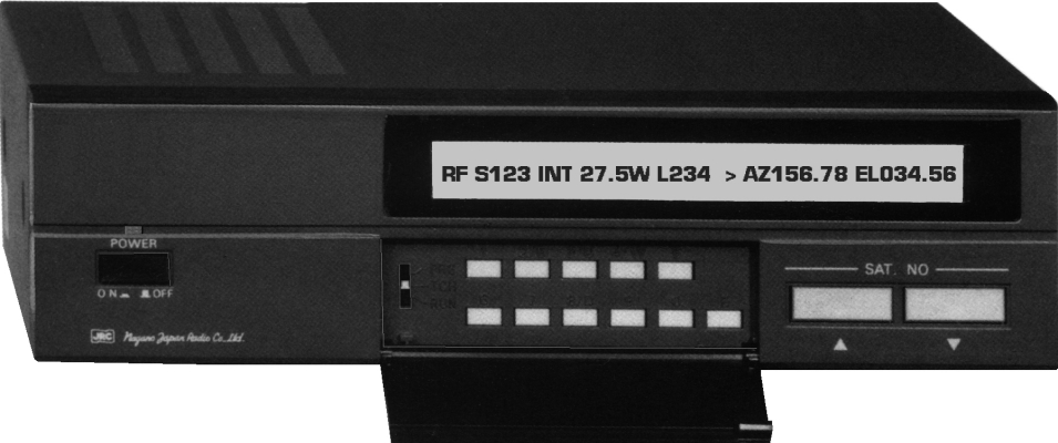
| D I S P L A Y – A R R A N G E M E N T | ||||||||||||||||||
| operating mode |
focus/ autofocus |
satellite position no. |
satellite name |
geostationary position |
relative field-strength pulse rate/speed |
rotor running direction |
azimuth angle |
elevation angle |
||||||||||
| R | F | S09 | AST | 019.2 | L208 | AZ123.5 | EL015.2 | |||||||||||
| CAUTION: Not all function are available on all versions and for each operating mode. | ||||||||||||||||||
| b. EXTENSIONS & OPTIONS | back to the beginning | |
|
 |
 |
 |
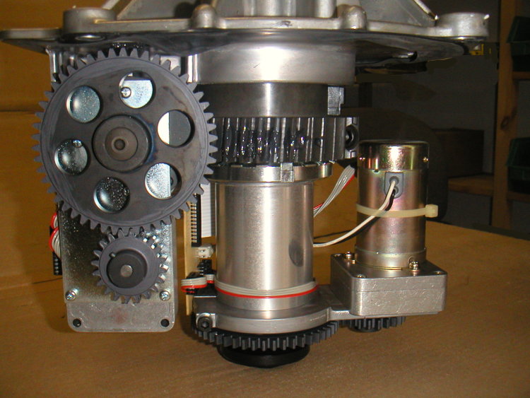
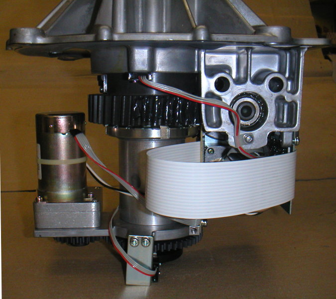
||
| gear parts inside rotor housing | rotor connection fixes | |||
| c. SYSTEM DESCRIPTION | back to the beginning | |
|
A system description showing the benefits of this rotor. The azimuth and elevation rotor system consists of an external antenna rotor EPR 203 and the indoor control unit EPS103. There are no additional parts needed between the mast mount and the dish.
The external rotor directs the parabolic dish fully automatically and microprocessor-controlled to one of the 345 pre-programmed satellite orbit positions. For this purpose two separate (!) 24 V motors are installed in a weather-proof cast aluminum housing of the external rotor assembly. They actuate the parabolic antenna in the desired direction horizontally in the azimuth and vertically in the elevation direction via reduction gears with high precision and less than 0.2° repetition accuracy.
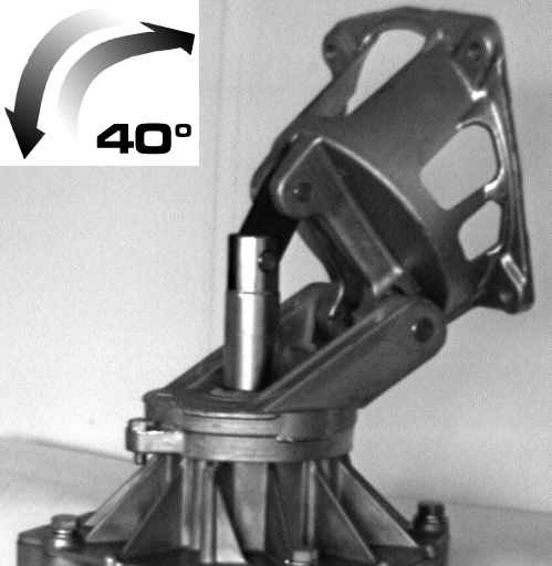
The aforementioned azimuth/elevation rotor system turns the parabolic dish antenna throughout a 180° azimuth range, which is wider than the theoretical and practical line of sight to the satellite orbit. The elevation range of the system is 40°. It remains to the user, where he uses this elevation range. In Europe you will mostly use the elevation span from 0 to 40°, near the equator this will be from 50 to 90°. Because the system carries out all operations with utmost silence contrary to some noisy actuator motors, it can be used at night without waking up neighbours, as it could be assumed from such a high-quality system.
This correction causes the control panel to re-calculate the positions of other pre-programmed satellites. Immediately you can switch over to any other wanted satellite – and the rotor will find it with good reception quality. If you have connected the AGC field-strength signal to the control panel before and adjusted it, this function will focus the chosen satellite to an optimum that you can not afford by hand. If you like, you can freely optimize every satellite signal by hand or auto-focus and store it. Installation is easy and simple. What about every day use? Via the front buttons you can switch to all satellites sequentially. Or take the number-pad for direct-access to the satellite-number. After that enjoy the remote-comfort of a polarmount-set with the perfect precision of the 2-axis rotor. If one or another satellite cannot be adequately received due to a slanted position of the antenna mast as a result of improper concrete casting, the computer program allows to individually correct azimuth and elevation of all satellite locations! For this purpose four keys of the keypad which is concealed by a cover plate are available for UP/DOWN and EAST/WEST adjustment to align the parabolic antenna under all circumstances to those angles which provide optimum reception. Of course all of these new values can be stored in the memory, so the entries must be made only once. But this is not the end of operating convenience, rather the beginning, e. g. entering a new satellite orbit location which is desired, but not yet stored in the memory. To do this, you select a sub program and the computer asks you which storage space you want to use. After selecting the desired space, you just enter the satellite location's degree of longitude in the orbit and perfect reception of this satellite is guaranteed. Because of its advances design, the computer is capable of performing calculations with persistent accuracy of all antenna locations, regardless if they are East or West of the Greenwich Zero Meridian. The computer can be used of course, to compile a table of angles for all pre-programmed satellite positions after entering the desired grid coordinates for large cities. Thus you can use your rotor computer for calculating the angles, under which the individual satellites can be received at each receiving station on the earth. But it does even more: It tells you, if the satellites are within the present range of vision or already hidden behind the horizon. To minimize fuel consumption older satellites are "inclined" in higher amplitudes. More than 50 % of all satellites are already in "inclination orbit". And their percentage is growing steadily. Permanent reception with greater antennas is not possible all over the time. One big advantage of this rotor system is the tracking of such satellites: Even before the TV viewer will recognize any loss of picture quality, the antenna will follow the satellites position automatically, quickly and perfectly. This system is superior to all sat-receivers with integrated 2-axis-control too! One of the most outstanding performance features of the system is its ability to cope with high wind speeds. Proved by finite elements calculation for material and shape of the load carrying parts. On the first look you recognize the high durability and stiffness of the aluminum die cast. But what's going on inside? Here some infos for the technicians, how the rotor is constructed: |
|
bearings
|
|
When you appreciate all the good things, don't forget the "nice trifles":
The advanced models however, are even more interesting:
|
 |
Here shown in DLR's GSOC (German Space Operation Center) in Oberpfaffenhofen the rotor worked with Yagi antennas for official use, managing duty traffic between the russian control center "ZUP" near Moscow and the "MIR" crew/astronauts. This was done in fullduplex using the lower part of the 2 m band. Communication via the 70 cm antennas was matter of the OM/HAM fellows (SAFEX) – but they were not used for official purposes. The permanent antenna tracking, done automatically, allowed transfer-connections ranging from 4 to 12 minutes in time intervals of 92 minutes. Using Eutelsat-IIF4 this connection persisted permanently between "MIR" and "ZUP" (Moscow) via "DLR" Oberpfaffennofen. |
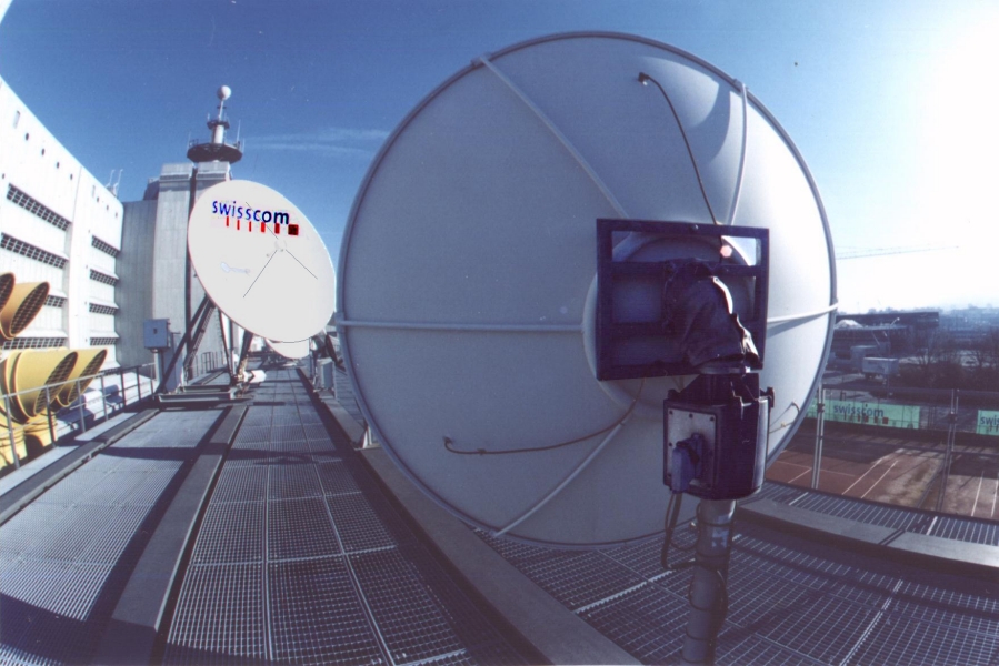 |
EGIS rotor in duty at "SwissCom" (in former times Swiss PTT), satellite-groundstation Zurich/Switzerland |
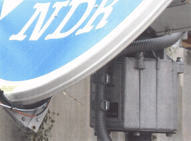 |
EGIS rotor featuring uplink antenna positioning in an "Norddeutscher Rundfunk" SNG truck |
| d. SPECIFICATIONS – PROFI-TRACKER CL | back to the beginning | |
| CONTROL COMPUTER: EPS-103 mod. | |||||||
| Line voltage | 220/110 V AC (12 V/24 V DC versions also available!) | ||||||
| Power consumption | approx. 180 VA | ||||||
| Data indication | LCD display | ||||||
| Programmable memory | up to 400 satellite orbit positions and names | ||||||
| Motor power supply | 24 V DC, for azimuth and elevation motor | ||||||
| Internal resolution: | Azimuth | 0.0100°/pulse | |||||
| Elevation | 0.0025°/pulse * | ||||||
| Pulse reading frequency | max. 500 Hz | ||||||
| Analog sampling rate | approx. 250 Hz | ||||||
| Dimensions (W x D x H) | 300 x 200 x 80 mm | ||||||
| Weight | 4 kg | ||||||
| Shipping box (W x D x H) | 39 x 29 x 15 cm | ||||||
| Temperature limits: | operational | –5 °C to +40 °C | |||||
| survive & storage | –15 °C to +60 °C | ||||||
| ROTOR UNIT: EPSR-203 mod. | |||||||
| Features | 2 separate motors for azimuth and elevation | ||||||
| Motor operating voltage | 24 V DC | ||||||
| Motor power consumption | max. 20 W | ||||||
| Pulse transmitting rate | max. 400 Hz | ||||||
| Cable 'control device to rotor' | 10 x 0.6 mm2 shielded (phone cable can be used) | ||||||
| Version 'ProfiTracker' needs separately shielded lines. | |||||||
| 4 x 1.0 mm2 (for motor power supply) – over 50 m wire 1.5 mm2, etc. | |||||||
| Control mechanism | pinion and gear transmission | ||||||
| Max. azimuth tracking range | 360° * | ||||||
| Max. elevation range | 90° * | ||||||
| Repetition accuracy | 0,2° (40° EL version) | ||||||
| 0,5° (90° EL version) ** | |||||||
| At the EL-swing endstops major deviations may occur! | |||||||
| Tracking speed: | Azimuth | approx. 4°/sec. | |||||
| Elevation | at 40°-stroke = 1°/sec. or 4°/sec. * | ||||||
| at 90°-stroke = 2°/sec. or 16°/sec. * | |||||||
| Usable carrying capacity | approx. 85 kg | ||||||
| approx. 60 kg using the 90° head extension (EL90) | |||||||
| (exceeding 50 kg a counter balance could be needed) | |||||||
| Cabinet | aluminum die-cast, weather resistant | ||||||
| Dimensions: | Diameter | approx. 318 mm | |||||
| Height | approx. 625 mm | ||||||
| Click here to see a dimension sketching! | |||||||
| Weight | 27 kg | ||||||
| Shipping box (W x D x H) | 75 x 34 x 41 cm | ||||||
| Dimension of mechanical connections: | Antenna mounting surface | see sketching | |||||
| Mast mounting surface | approx. 240 mm Ø – 4 threaded (bolts are supplied) | ||||||
| Max. permissible antenna diameter | for 40° or 50° EL version up to 2.5 m (8 feet) * | ||||||
| for 90° EL version up to 1.8 m (6 feet) * | |||||||
| Wind speed | 62,5 km/h (41 MPH) during operation, | ||||||
| 129 – 160 km/h (80 – 100 MPH) depending on antenna diameter in quiescent state | |||||||
| (strength proof by finite elements calculation) | |||||||
| Temperature limits: | operational | –20 °C to +65 °C | |||||
| survive & storage | –30 °C to +65 °C | ||||||
| * | = | depending on design |
| ** | = | Greater errors may occure in excessive lift positions at the end of the moving range by overload, too. |
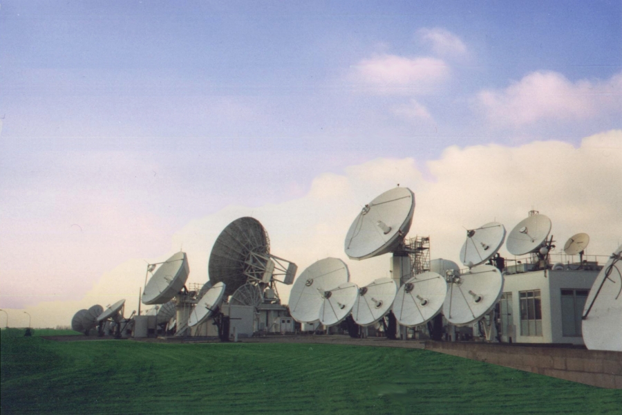
| Experiences with larger antennas |
 |
 |
 |
||
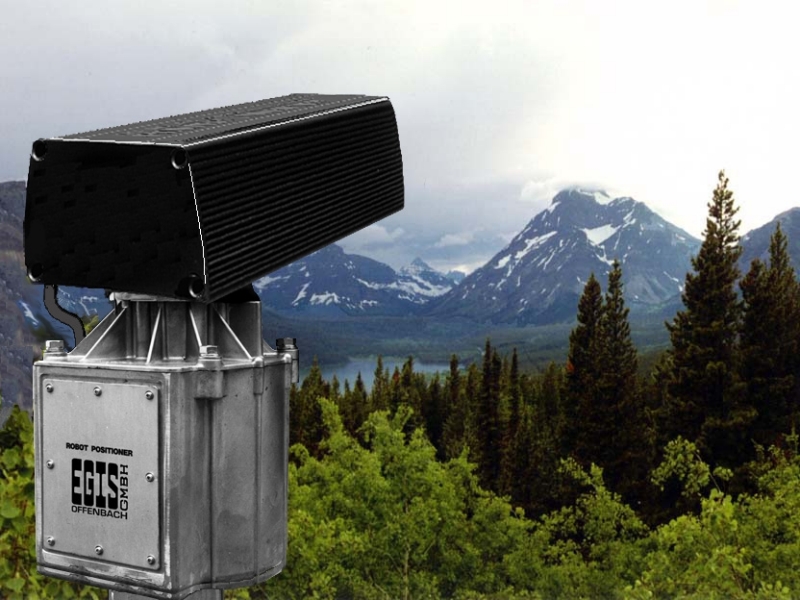
| University Budapest/Hungary. Institute for High Frequency Techniques. | Right here (in the alps) a live weather panorama cam follows the terrain profile controlled in two axis via RS-232-C interface. | Mesh antenna 3.1 m Clickable link: example of a mesh antenna attachment |
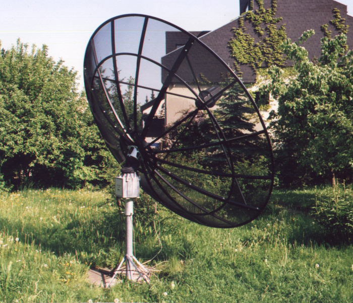 |
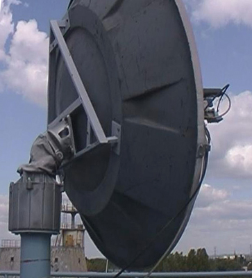
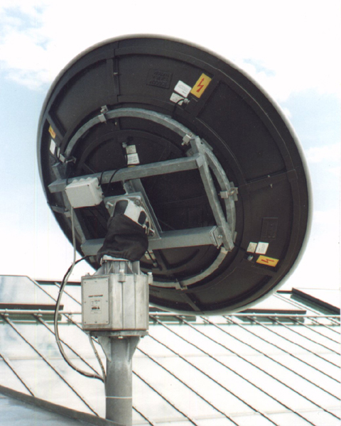
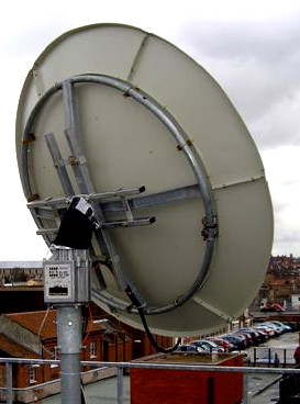
Rotor with 3.1 m mesh-primefocus antenna for C-band reception |
 |
EGIS-Rotor (AZ = 360°; EL = 90°) in duty at the department for "Astronautic and Space Science" at the "Deutsches Museum", Munich. Weather satellites (LEOs) are scanned permanently. |
 |
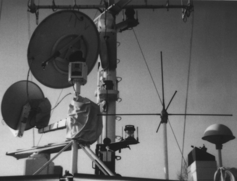 |
Rotor in use with 1.5 m parabolic antenna made by Kathrain on trawler |
||||
| SNG truck of "Antenne Bayern", Munich/Germany in position to uplink news | ||||||
 |
Shown here is a heated 1.5 m parabol antenna from Hirschmann (Technical Museum Vienna/Austria) |
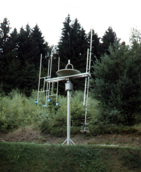 |
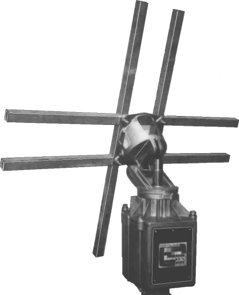
Shown here is a rotor (360° AZ/90° EL) supporting a 90 cm parabolic bowl antenna in the center. A 4,8 m long cross Yagi antenna for the 70 cm UHF- band and a Sat S-band antenna (13 cm/2 GHz) are also positioned by means of a crossbeam of 180 cm length. |
| MORE IMAGES AND INFORMATION |
| e. PRICE LIST | back to the beginning | |
| VERSION | | (excl. VAT) EURO | |||||||||
| PROFI-TRACKER CL | Antenna positioner with basic scope | 4 397.00 | ||||||||
| OPTIONS | | (excl. VAT) EURO | |||||||||
| b1 'DATA' | Interface (RS-232) for version FOCUS or PROFI TRACKER | 998.00 | ||||||||
| b2 'GPS-H-T1' | GPS-Reciever incl. software modification | 690.00 | ||||||||
| is only supplied in combination with Data-Interface | ||||||||||
| b3 'MOTION CONTROL' |
Servo \ speed control | 1 320.00 | ||||||||
| b4 'AZ360' | Extension to 360° azimuth rotation range | 998.00 | ||||||||
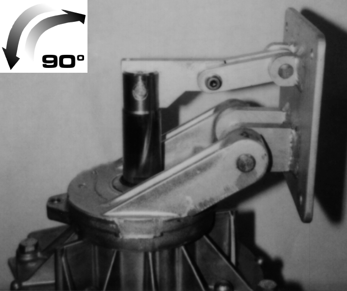
| b5 'EL90' | Extension to 90° elevation angle | 998.00 | ||||||||
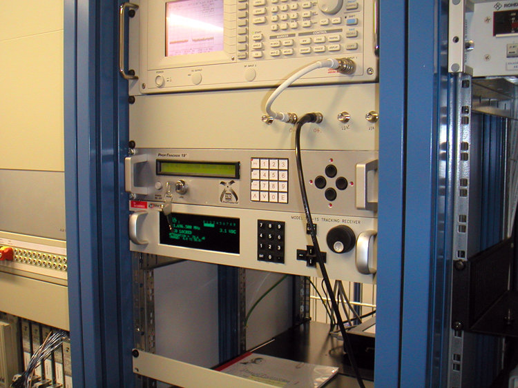
| b6 'GR-19' | PROFI-TRACKER-control unit fitted into a 19" rack mount (2 HE) (image H) | 1 320.00 | ||||||||
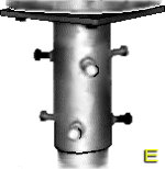
| b11a 'MA-35' | Mechanical interface between rotor and mast (max. 89mm Ø mast) | 298.00 | ||||||||
| incl. mounting hardware (image E) | ||||||||||
| b11b 'MA-50' | as above, but for max. 128 mm Ø mast | 398.00 | ||||||||
| incl. mounting hardware (image E) | ||||||||||
| b12 'PT-T2' | Universal connecting link between parabolic antenna and rotor head | 398.00 | ||||||||
| Pot-galvanized, made from square tubing (50 x 30 x 2 mm); mounting hardware for rotor head installation is included. Length: 1 m. Suitable for parabolic antennas of up to 2 m (7 ft.) diameter. (image Z). | ||||||||||
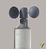
| b13 'Wi-S1' | Wind-speed-sensor/shell-anemometer | 423.00 | ||||||||
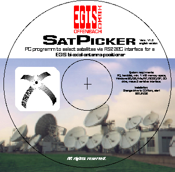
| b14 'SatPicker I' | PC software on CD for selection of geostationary satellites via RS 232 C interface | 298.00 | ||||||||
| Modification and upgrading of former system types is possible to a limited extent (advice to soft- and hardware expansions). Please contact us for additional information. |
|
Retailer inquiries are welcome! Contact us on your special application problems!
Technical improvements are subject of change! |
| CONTENT: base version | extensions/options | system description | specifications | price list | news |
| IMAGES: controls and connectors | gear parts and options || MORE IMAGES AND INFO |
| EGIS Cloud |

|
E G I S
EQUIPMENT GESELLSCHAFT für INTERN. ELEKTRONIK SYSTEME GmbH |
Flutstraße 34 – 36
D–63071 OFFENBACH/MAIN Tel.: 069 / 85 83 27 Fax: 069 / 85 78 63 |
| << Homepage | 20 minutes from Airport Frankfurt – 20 minutes to Frankfurt City | E-Mail: Sat@egis.eu |

